
The term robot was introduced to the world in 1921 in a Czech play, Rossum’s Universal Robots. The word is derived from a term meaning “forced labor” and was used to describe an artificial person.
Fast forward almost 100 years to 2018 and not all roboticists agree on what exactly makes a robot a robot.
However most would agree that robots are made of the following main components: a control system (such as the CPU of a computer), sensors (such as infra-red, sound, pressure, …), actuators (usually a motor), a power supply (such as batteries) and end effectors (such as a gripper or a tool). These parts work together so that the robot can take in information from the world around it and respond appropriately.
Learning how each component works and how to wire them all together in order to build a functioning robot is a long-term project. To start, it is helpful to learn about the main components on their own. In this issue we will begin to understand actuators commonly used in basic robots.
Technically, an actuator is the part of a machine that is responsible for its motion. Most robots use motors as actuators.
There are quite a variety of motors available for beginning projects, and even more as we delve deeper into robotics. Perhaps three of the most common low-price motors are simple DC motors, stepper motors, and servos. These three groups of motors themselves encompass several subgroups. How can we know what motor to use for what purpose?
Simple DC Motors
DC motors can be fun to use in beginning robotic projects. Hobby motors are cheap and come in many kits. The shaft spins at a high speed which can only be directly controlled by changing the voltage. This is done by increasing or decreasing the number of batteries (within a range of about 3 – 6 volts), or connecting the motor to a potentiometer in order to alter the voltage. To reverse the direction of the spin, reverse the connection to the positive and negative ends of the batteries. Try out either of the projects below to get a feel for these motors:
Blending colors: Cut a circle out of a sheet of white paper. Make a colorful design on the circle and attach it to the shaft of the motor. Connect the motor to a power supply (3-6 volts) and watch the colors blend before your eyes.

DrawingBot: Find a small cardboard box or a strawberry crate to use as the “chastise”. Glue or zip tie a marker to each corner, with the ink tips pointing down. Attach a small weight, ideally off center, to the motor’s shaft (a piece of unmelted hot glue stick works well). Connect the motor to a power supply and place the bot on a large piece of paper. Turn it on and watch the bot “draw” as to jitters around the paper.

Similar to these fast spinning hobby motors are slower spinning TT motors. Their speed is also controlled through voltage and they only spin in one direction until the circuit is rewired as well. However, they spin much more slowly than the DC motors describe above. As such, TT motors are better suited for making wheels spin at a reasonable rate, or making simple robots walk.
Interested in connecting your motors to an Arduino and controlling them with code? It is not wise to connect motors directly to a microcontroller. However, it is not particularly difficult to wire the motors to a motor controller, or an H bridge, that can then be connected to an Arduino. Doing so makes the speed and direction of these simple DC motors controllable through a few lines of code, enabling them to be used in a more functional robot.
Stepper Motors
Stepper motors have an interesting feature not found in the DC motors described above. The shaft moves in “steps”. Stepper motors differ in the number of steps required to make one full rotation, however once you figure this number out for a particular motor, you can tell the motor to rotate a certain number of steps and then stop or reverse direction. This is usually done by using the stepper together with an Arduino and writing a few lines of code. So long as it remains connected to a power source or is told to move again, it will hold its position.
This feature is not so useful in most RC planes and cars, but it comes in handy in both computer printers and 3D printers, as well as in the autofocus of many camera lenses. The speed at which the shaft rotates a given number of steps can also be controlled. As such, when building part of a robot that needs to rotate through a certain angle at a given speed, a stepper motor may worth considering.
One idea for a beginner project using a stepper motor is to make a motorized “elevator” system. Through a bit of guess and check work, figure out the number of steps required by the motor to pull the elevator to a desired height. For example in the treehouse shown below, we found that it takes approximately 32 steps for the elevator to reach the platform of the treehouse. Once it reaches the desired height, we programmed it to wait five seconds, delay(5000), and then rotate 32 steps in the reverse direction, back to the ground. It should be noted that this code is in a loop so it will repeat over and over until the power is switched off. Due to the nature of Arduino, there is not a great way to avoid this.

Code for Stepper Motor Elevator

Servo Motors
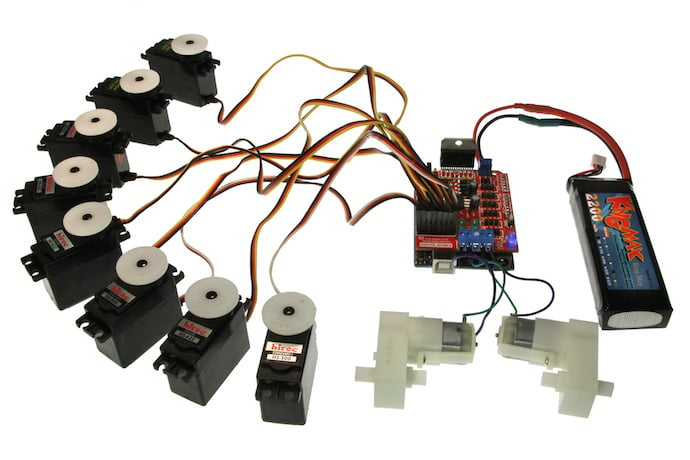
Of the three types of motors introduced in this article, the servo may be the most commonly used in robotics projects.
An important feature of servo motors that distinguishes them from other motors is that there is a small circuit board within them. Attached to that circuit board is a positional sensor that tells the circuit board how far the shaft has rotated. As such, servos can be controlled with a program written for an Arduino that tells them exactly how far to rotate. This may sound similar to programming a stepper motor. However the stepper motor doesn’t actually know how much is has rotated at any time. Instead, it knows how many pulses have been sent. If by chance a pulse was sent but the shaft did not actually move (perhaps it was obstructed), the stepper motor does not have a feedback mechanism to let it know the current position. By comparison, the servo motor keeps track of its location at all times.
Some servo motors only have a range of 180 degrees; After they have rotated through half a circle they rotate back in the other direction. One common application is to control robotic hands. On the other hand, continuously rotating servos rotate 360 degrees and can be used to control the wheels of a rolling bot.
Most robotics experts would not consider wiring up a motor, and even programming it to follow simple instructions, to be building a complete robot. These creations are better classified as electronics projects as they lack sensors to take in information from the world and react to it. However, it would be difficult to build a fully functional robot without first completing a few electronics projects. By familiarizing yourself with several basic motors, you are well on your way to creating your own robot!
Learn More
What is a Robot
https://www.wired.com/story/what-is-a-robot/
Guide to Motors
https://www.circuito.io/blog/arduino-motor-guide/
Stepper Motor Tutorial
https://www.sparkfun.com/tutorials/400
How to use a Stepper Motor
http://www.instructables.com/id/How-to-use-a-Stepper-Motor/
DC Motor Control Tutorial
Servos Explained
https://www.sciencebuddies.org/science-fair-projects/references/introduction-to-servo-motors