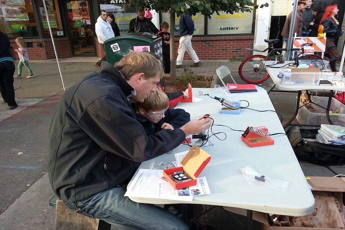
We looked at soldering in this article previously and it’s an excellent skill to have and can open up a trove of electronics kits and learning. At some point in your soldering you will want to solder a circuit that is one of your own creation and isn’t a kit with a PCB.

One of the ways to make a circuit permanent is to use a soldering prototyping board, or “perfboard”. Perfboard is the most common name but sometimes these types of boards can be called “vero board”, “strip board” or “proto board”. There are a few variants in the way in which they are laid out but the principals of use are similar. They are a tough board that has copper pads on one side and a regular grid of holes to fit electronics components through for soldering. Many components are designed so that their leads or pins are arranged at 0.1” or 2.54mm intervals and so most perfboards use this spacing.
One of the most common forms of perfboard has all the holes in a row connected via a continuous copper strip. This means that anything soldered to a single row is electrically connected. Other types of prototyping board have every hole separate with a small coper pad for each hole. This means that until you add something connecting one hole to another whole everything is electrically isolated. It’s common with this second type to use component leads and bits of wire to run around making the connections. It can look a little messy but it still can create a solid circuit. Finally there are sometimes prototyping boards with different arrangements and groupings of connected holes. One style in particular are those that emulate an electronics breadboard layout, these can be super handy if you have created a circuit on a breadboard and you can transfer it to the permanent board using exactly the same layout.

When using the prototyping board with continual strips of copper connecting rows you can create more complex circuits by cutting the copper tracks when required. You can make the cuts carefully using a variety of methods, the recommended tool is a track cutter which is essentially a drill bit in a screwdriver handle that you can place the tip of in a hole on a track and then twist back and forth to cut away the copper at that point. Alternatively people use a plain drill bit, or even carefully create cuts using a craft knife or even a rotary “dremel” type tool.

However you create a cut it’s important that you check you have cleared all the copper in the gap as even a tiny piece of copper can make a short circuit. It’s a good idea to visually inspect the trace using a magnifying glass. Also if you have a multimeter that has a continuity mode you can check that there is no connection between points either side of the cut, select the continuity test mode on the multimeter and touch a probe to either side of the gap, if it doesn’t bleep then you have no connection. If your circuit design uses a microchip you will need to cut a long gap in between the pins underneath the chip so that the opposing pins aren’t connected/shorted. You can do this again with a dremel type tool or carefully do this with a craft knife.

Using a strip layout perfboard you will also at some point want to create a link across the board which is impossible to make just by using the tracks. For this you will use a jumper wire. This is very similar in principle to wiring between the points on a prototyping breadboard. The easiest type of wire to use is one with a single solid core, cut a piece to length and trim the sleeve off the ends to solder through the holes. You can get quite creative with your routing!


Using perfboard can be very efficient. We made this simple circuit with 5 LED’s each with a current limiting resistor. All the resistors are connected to the positive strip and all the cathodes on the LED’s are connected to the negative strip. We only had to make cuts between each LED on the strip where the anode and the resistors are tied together. The circuits you can make this way are tough as most perfboards are made from either fibreglass or phenolic resin and, don’t forget, so long as you aren’t in a part of your design where it would damage the circuit you can cut perfboard into interesting shapes and drill mount holes etc. It really is a very versatile way to create circuits.
Learn More
How to make a simple circuit
https://www.weirdunsocializedhomeschoolers.com/how-to-make-a-simple-circuit/
Simple circuit using battery
https://sciencing.com/make-simple-circuit-kids-using-battery-wire-12044826.html
Making a simple circuit (video)
https://www.youtube.com/watch?v=oDUAvaXsK1g
Simple electronic projects
https://stemeducationguide.com/simple-electronics-projects/
Foil circuits
How to make a circuit (video)
https://www.youtube.com/watch?v=js7Q-r7G9ug

