
What will you need for this project?
- Any computer with an Internet connection
- A micro:bit (http://microbit.org/resellers/)
- Some headphones
- 5 x Crocodile clips
- A 10k potentiometer
- An LED
All of the code for this project as well as circuit diagrams can be found at https://github.com/lesp/KidsCodeCS-microbit/archive/master.zip
Introduction
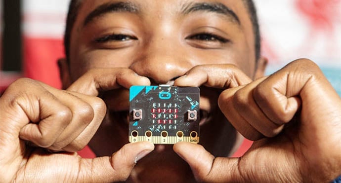
The micro:bit was released in 2016 as a low cost micro-controller board for children in the United Kingdom to learn the basics of coding. Over 1 million units were given to children starting their first year of high school, and teachers were encouraged to use the boards to open up new possibilities in lessons.
The board is nowhere near as powerful as a Raspberry Pi, not even the Pi Zero. Rather this is a small board akin to an Arduino. It has a 16Mhz ARM processor, 16Kb of RAM and 256Kb of flash memory to store your code. Code is written using an online editor, in various languages more on that later, and then copied to the micro:bit which appears as a USB flash drive.
So while the micro:bit may not be a powerhouse, it has a built in range of sensors and connectivity that we can use in our projects. It comes with Bluetooth and a radio to send packets of data over a short range radio network. There is also a built in accelerometer to determine how the micro:bit is being held enabling basic gesture control. We have a compass, a temperature sensor, a 5 x 5 LED matrix and 2 buttons.
The GPIO, General Purpose Input Output pins are a series of 5 holes in the lower part of the board. Number 0,1,2 and 3V, GND these pins can be connected using crocodile clips. The smaller pins between each hole are further GPIO pins which require an adapter board.
In this tutorial we shall create 3 projects that utilise the different sensors and inputs of the micro:bit.
We shall be covering the following concepts
- Loops
- To repeat portions of code
- Input
- Using gestures to control music and produces messages
- Using analog electronic components to change our output
Getting Started
To code our project we shall open a web browser and visit https://pxt.microbit.org and we start with a blank project.

pxt 101
The pxt editor is block based, meaning that we click on the block menu, just left center of the screen. To open a menu, click on it and you will see the blocks that it contains. This will show an expanded window that will briefly lie over the coding area, to the right of the screen. Blocks can be moved from the menu to the coding area and connected in the same manner as with Scratch.

On the left of the screen we have an interactive micro:bit simulator that enables us to test our code before we deploy it to the real hardware. Very handy!
The block menu

Project 1: Stop shaking me!

We start the code for this project by first clearing the “on start” and “forever” blocks from the coding area, drag them one by one to the blocks menu and drop them to tidy them away. Now go to the Input menu and drag the “on shake” block to the coding area. This is our input that will trigger the code that we will write inside this block.

So what will happen when we shake the micro:bit? Well firstly we shall scroll a message across the LED matrix. For that we need to use the “Show string” block from the Basic menu. Drag this block so that it is inside “on shake” Now change the text to say “Stop shaking me!!!” Again from the Basic menu, drag a “pause (ms) 100” block, and connect that to the previous block, but change the value to 500ms, half a second.
##project1-step3.png

Now go back to the Basic menu and look for the “show icon” block, connect this to the previous block. These icons are small pixel images that use the LED matrix to display an image. You can change the icon by clicking on the small drop down arrow to the right of the icon. We changed ours to an angry face as our micro:bit did not like being shook.
Our last block is another “pause (ms) 100” from Basic, again we change the value to 500ms, half a second.
With the code now written, we can download the code to our computer. Then connect your micro:bit to your computer using a micro USB to USB lead. Your micro:bit will appear as a USB flash drive. Simply copy the downloaded file to the flash drive and your micro:bit will reboot. When ready give it a shake and you will see the code come to life!
Project 2: Analog Input
The micro:bit comes with GPIO pins that are both digital (1,0 on or off) and analog (0,1023) referring to a voltage. Analog components are used quite frequently as they are precise. In this project we shall use a 10k potentiometer to control the brightness of an LED.
For this project we shall need the 5 crocodile clips, the LED and the potentiometer. They will need to be wired as follows. The long leg of the LED, the Anode, need to be connected to Pin1 of the micro:bit. The shorter leg, the Cathode is connected to GND of the micro:bit. The potentiometer requires that the first leg be connected to 3V, the third leg to GND, and the center leg connected to Pin 0 of the micro:bit.

Here is the circuit diagram for project 2. Take your time and carefully make each connection.
##project2-step1.png

Create a new project by clicking on Projects in the top left of the screen. When the new project is ready to edit, remove all of the blocks, except for “forever” as we will need that. Now go to the Pins menu and look for “analog write pin to 1023”, drag this and place it inside the forever loop. Then go back to the the Pins menu and look for “analog read pin”, drag that and place in over the “1023”.
Change the analog write pin value to P1, the pin connected to the long leg of our LED. Then change the analog read pin to P0, the output from our potentiometer.

Download the code for this project and copy it to your micro:bit just as we did for Project 1. Your micro:bit will reboot and now you can use the potentiometer to control the brightness of the attached LED. And it only took one line of code!
Project 3 – A Compass controlled musical instrument
For our final project we shall create our own musical instrument using the micro:bit. Inside the micro:bit is a compass that can detect magnetic north. We shall use the compass as an input to trigger a tone to be played depending on the orientation of the micro:bit.
For this project you will need 2 crocodile clips and a pair of headphones with a 3.5mm jack.

Connect the GND pin to the lowest part of the headphone jack using the crocodile clip. Then connect the tip of the headphone jack to Pin 0 of the micro:bit using the other clip. Sound will only play from headphone.

Create a new project and remove every block except “forever”.
Our first block is from the Logic menu, and it is “if true, then” this block uses conditional logic, a logic that checks to see if a certain condition is correct, True, and if so the code is executed. Drag this block and place it inside the forever loop.
Now we need to expand the number of conditions to test, and to do this we need to click on the small “gear” icon in the top left of “if true, then” then change the contents so that we have 1 if, and 3 else if. Then click on the “gear” icon to go back to the code. Now we can test 4 conditions, enough for the 4 main compass points (North ,East,South, West)

Our next block is located in Logic and it is “0 = 0” this compares the value on the left, to that on the right. Place this on top of the True part of our “if” test. Then change the “=” to “?” meaning less than or equal to. Change the right “0” to read “90”. So now our code knows that we want to compare 90, a quarter of the total number of degrees for our compass, to another value. This value can be found in the Input menu and it is called “compass heading ()” Drag this into the remaining “0” space. So now our compass heading is compared to see if it less than or equal to 90 degrees.

Now lets replicate this code for the first of the remaining 3 conditional tests. These tests will be activated should the previous test return false. For the first else if test we need to go back to the Logic menu and drag a “__ and __” block, connecting it to the first else if. Then we drag the “0 = 0” block again from Logic and place that inside the first blank of “__ and __”. Next do the same for the second blank “__ and __” space. Change the first “=” to “>” and then change the second to “?”. In the second 0 of each “0 > 0” and “0 ? 0” change the values as follows. The first is 90 and the second is 180. In the first 0 of each, go to Inputs and drag the “compass heading ()” block just as we did previously.

Now we need to do the same for the remaining 2 conditions. Remember to update the values! Once completed we now have all of the conditions needed for our project to use as inputs for the instrument.

For each of the conditional tests we now need to add a tone that will play when the condition is true. We can find the tone block in Music. Drag “play tone Middle C for 1 beat” and place it inside the first blank “then” space which is linked to the if the micro:bit is facing between 0 and 90 degrees. Change the beat so that it plays every half beat, giving us a quicker beat for the music. You can test to see if this works in the simulator, located on the left of the screen. Click on the play button and then rotate the micro:bit logo, located on the top of the simulator board, it looks like a pair of eyes. Once the logo is between 0 and 90 degrees it should play a note.

Now we need to add tones for the remaining conditions. We added Middle D, E and F, but you can add anything that you feel like.
Our code is now complete! Download the code as we did in the previous Projects and when ready rotate the micro:bit to hear the tones being played!
Congratulations you have completed 3 introductory projects using the micro:bit
During these projects we learnt that
- Input does not just mean keyboard and mouse, it can be a gesture, a compass direction or a sensor.
- Writing code for the micro:bit is easy using the pxt editor.
- We can interface electronic components with the micro:bit.
- We can accomplish a lot of computer science using a $20 computer.
How could we take this further?
There are many resources available online but the best are from the BBC, in this next project you can help The Doctor from TVs Doctor Who to defeat the Daleks by building your own Sonic Screwdriver, powered by the micro:bit http://www.bbc.co.uk/programmes/articles/52yF6JCCn1X2L4HKBQtgWlP/doctor-who-and-the-micro-bit-mission-sonic
Learn More
micro:bit Foundation
http://microbit.org
http://microbit.org/resellers/
micro:bit Resources Page
https://kidscodecs.com/resources/microbit/
13 Top BBC micro:bit Projects
http://www.itpro.co.uk/desktop-hardware/26289/13-top-bbc-micro-bit-projects
The Watch Activity
https://www.microbit.co.uk/blocks/lessons/the-watch/activity
micro:bit gadgets