


Unlike terrain maps which might have mountains, streams, buildings, trees, and other pieces, circuit diagrams only have two pieces:
- Electronic components — each component has a data sheet which describes all possible connections to the component.
- Connections — each connection is a line to connect one component with another.
It’s possible to build an electronic project by reading a circuit diagram and using it to identify then make all the connections needed from one component to another. An engineering degree is not required. Circuit diagrams also are widely available for many different projects. Components also can be found easily.
This article provides a high level overview of circuit diagrams and how they work. The Learn More section below provides links to more detailed descriptions and resources.
Also note there is a difference between circuit diagrams, which describe a detailed electronic system, and a schematic diagram which may describe the same system but also include concepts and other abstract details. This article describes circuit diagrams used to build electronic projects.
Connections
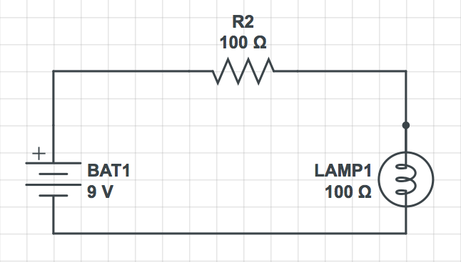
Circuit diagrams map the flow of electricity through a system. The flow must complete a circuit, for example, from the positive node on a battery to a resistor to a lamp and back to the negative node of the battery. This is the simplest form of a circuit diagram.
From this simple circuit, you add other elements, in this case, a single pole single throw (SPST) switch to turn the circuit on or off which turns the lamp on or off:
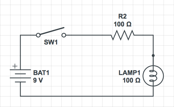
(Diagrams created with CircuitLab.com, link below)
The lines that connect each part of this diagram, from the positive pole of the battery on the left to the light on the right and back to the negative pole of the battery, could be wires or copper laid out on a circuit board.
More interesting is the fact connecting the positive and negative poles of a battery to create a circuit causes a collision of positive and negative electrons in the lamp bulb which, in turn, causes the light filaments to glow. While the circuit diagram shows conventional circuit flow, from positive to negative poles from the power source, the reality of how electrons flow is slightly different.
There is more complexity in these simple diagrams. For example, the voltage in ohms would be set to reflect the needs of the system and/or the capabilities of the component. My diagrams above are only to illustrate the idea of a circuit.
From this elementary circuit diagram, you can diagram then build a wide range of electronics projects, from simple light switches and bulbs to sound systems to computers. They’re all based on this elementary diagram of a complete circuit from power source through electronic components.
Components
There are many different components that show up in circuit diagrams. A complete diagram includes a data sheet to describe all connections and components which can be used as a parts list to buy components. Here are some common types of components you might see in a circuit diagram.
| Component | Description |
|---|---|
| Battery | Provides electric current for the system. Could be replaced with AC or DC power from a wall socket. |
| Capacitors | Used to temporarily store an electrical charge. |
| Diodes | Lets current flow in only one direction, from a positive terminal (anode) to a negative terminal (cathode). |
| Resistors | Reduce (or resist) current flow which lowers voltage flowing through a circuit. |
| Switch | Controls power on or off, as well as activate other parts of a system that provide features. |
| Transistors | Amplify current flow which increases voltage through a circuit. |
History of Schematic and Circuit Diagrams
The history of electronic components goes back at least to the invention of capacitors by Leyden in 1745. However, simple batteries may have been in existence for at least two thousand years, for example, the Baghdad Battery which appears to use copper, iron, and bitumen to generate electron flows. While some say the battery is evidence of ancient aliens, if it is a battery, more likely it was used to electroplate gold on to silver objects. I first came across a mention of this battery while reading the memoirs of Ibn Battuta, a Berber from North Africa who traveled from Morocco to China and back from 1325 to 1353. While he started out on a hajj, he spent his adult life in Egypt, Syria, Iraq, India, Indonesia, and China. His book describes a lot of interesting technology.
But I digress…
In more modern times, circuit diagrams helped early developers of computer systems to build electronic systems to specifications, as well as reference earlier designs to improve them. Today circuit diagrams are used mostly to create electronic systems, either by individuals or through mass production.
The history of circuit diagrams involves people finding common ways to describe electronic components. In 1909, for example, the International Electrotechnical Commission (IEC) started work to develop a common set of terms and symbols to describe electronics. Symbols were created for measurements and graphic representations of electronic objects. Over time, electronic symbols have evolved to represent use in different countries as well as different time periods.
How Do You Create a Circuit Diagram?
While there are software tools you can download on your computer, perhaps the easiest way to create a circuit diagram is with online tools CircuitLab and Scheme-it. These tools let you drag and drop components, make connections, and perform other tasks. However, you need to take a course or get input from online communities to ensure your design is efficient and works. And you may have to pay to download any completed design which is comparable to paying for software to download on your computer.
Learn More
How to Read Circuit Diagrams
http://makezine.com/2011/01/25/reading-circuit-diagrams/
http://www.instructables.com/id/HOW-TO-READ-CIRCUIT-DIAGRAMS/
http://www.epemag.net/how-to-read-circuit-diagrams.html
How to Draw Schematic Diagrams
http://opencircuitdesign.com/xcircuit/goodschem/goodschem.html
Circuit Diagram Software Tools
http://www.circuitlab.com
http://www.digikey.com/schemeit
http://opencircuitdesign.com/xcircuit/welcome.html
http://www.epanorama.net/links/software.html
Circuit Diagram Libraries
Components
http://en.wikipedia.org/wiki/Circuit_diagram
http://www.dummies.com/how-to/content/switches-in-electronic-circuits-poles-and-throws.html
http://en.wikipedia.org/wiki/Resistor
http://en.wikipedia.org/wiki/Transistor
http://en.wikipedia.org/wiki/Capacitors
http://en.wikipedia.org/wiki/Diodes
http://www.dummies.com/how-to/content/basic-electronic-components-and-what-they-do.html
History of Electronics
http://en.wikipedia.org/wiki/Electronics
http://en.wikipedia.org/wiki/Electronics#History_of_Electronics_Timeline
http://tc3.iec.ch/history/tc3_history.htm
Baghdad Battery
http://en.wikipedia.org/wiki/Baghdad_Battery
http://ibnbattuta.berkeley.edu/
http://www.fordham.edu/halsall/source/1354-ibnbattuta.asp (edited)
http://www.fordham.edu/halsall/IHSP-travelers.html